1. Identify the Basic Heat Transfer Requirements of the Industrial Process
1.1 Determine the Heat Transfer Application
First, identify the specific purpose of the heat exchanger in the industrial system, such as heating, cooling, condensation, or evaporation. Different applications have different requirements for equipment structure and operating parameters. Clearly defining the application helps determine the appropriate heat exchanger type and design.
1.2 Identify the Hot and Cold Fluids
It is important to understand the types of fluids flowing through both sides of the heat exchanger, such as water, steam, thermal oil, chemical solutions, or other industrial fluids. Different fluids have different physical and chemical properties, which directly affect heat transfer performance and material selection. For corrosive or chemically aggressive fluids, material compatibility must be carefully evaluated.
1.3 Determine the Inlet and Outlet Temperatures
The inlet temperatures of both fluids and their required outlet temperatures are essential parameters in heat exchanger selection. These temperatures determine the available temperature difference and influence the required heat transfer area and equipment design. When the temperature difference is relatively small, a larger heat transfer area may be required to achieve the desired performance.
1.4 Calculate the Required Heat Duty
The required heat duty should be calculated according to the actual industrial process requirements. It can generally be estimated using the fluid flow rate, specific heat capacity, and temperature change. Heat duty is one of the most important factors in determining the equipment size and heat transfer area. A reasonable design allowance should also be considered to accommodate normal variations in operating conditions.
2. Select the Heat Exchanger According to Operating Pressure and Temperature
2.1 Evaluate the System Operating Pressure
Shell and tube heat exchangers are commonly used in medium- and high-pressure industrial applications. However, their actual pressure capacity depends on the equipment structure, material, wall thickness, and manufacturing standards. During selection, the design pressures of both the tube side and shell side must be clearly specified. The equipment must be designed to meet the pressure requirements of the entire process system.
01
2.2 Consider the Operating Temperature Range
High-temperature industrial processes require shell and tube heat exchangers with suitable heat-resistant materials and structural designs. The materials, sealing components, and tube-to-tubesheet connections must be capable of withstanding the actual operating temperatures. Temperature changes during equipment startup, shutdown, and normal operation should also be considered.
02
2.3 Evaluate Thermal Stress Caused by Temperature Differences
When the temperature difference between the hot and cold fluids is large, different thermal expansion rates may occur between the tubes, tubesheet, and shell. Long-term thermal stress can cause deformation, damage to connections, or leakage. For applications involving large temperature differences, floating-head or U-tube designs may be considered according to the engineering requirements.
03
2.4 Consider Pressure and Temperature Fluctuations
In some industrial processes, operating pressure and temperature are not constant and may change with production loads. During equipment selection, the possible maximum and minimum operating conditions should be identified. A suitable design helps maintain stable operation under different process conditions.
04
3. Select Tube and Equipment Materials According to Fluid Properties
3.1 Consider the Corrosiveness of the Fluids
Different industrial fluids have different effects on metal materials. Carbon steel or stainless steel may be suitable for ordinary cooling water and many general industrial fluids, depending on water quality and operating conditions. For fluids containing chlorides, acidic substances, or other corrosive components, materials with appropriate corrosion resistance should be selected.
3.2 Choose Suitable Heat Transfer Tube Materials
Common heat transfer tube materials include carbon steel, 304 stainless steel, 316 stainless steel, titanium, and other corrosion-resistant alloys. 304 stainless steel is suitable for many general industrial environments, while 316 stainless steel generally provides better corrosion resistance in certain chloride-containing environments. Titanium is commonly used in applications such as seawater cooling, where high corrosion resistance is required.
3.3 Consider Fluid Viscosity and Flow Characteristics
Fluid viscosity affects the flow conditions and heat transfer performance inside the heat exchanger. High-viscosity fluids generally produce greater flow resistance, so tube diameter, flow velocity, and heat transfer area must be properly designed. For fluids containing suspended particles or fibers, the possibility of tube blockage should also be evaluated.
3.4 Evaluate Fluid Cleanliness
If the fluids contain impurities, solid particles, or substances that easily form deposits, fouling and blockage may occur inside the heat transfer tubes. During selection, filtration equipment should be considered, and suitable tube diameters and flow velocities should be determined according to fluid characteristics. For applications with a high fouling tendency, priority should be given to designs that allow convenient mechanical cleaning and maintenance.
4. Choose the Appropriate Shell and Tube Heat Exchanger Design
4.1 Fixed Tubesheet Heat Exchanger
A fixed tubesheet heat exchanger has a relatively simple structure and generally lower manufacturing costs. It is suitable for applications with relatively small temperature differences and clean fluids. Since the tubes are fixed to the tubesheets, mechanical cleaning of the shell side can be difficult. When selecting this design, the shell-side fouling tendency and the difference in thermal expansion between the tube bundle and shell should be carefully considered.
01
4.2 Floating Head Heat Exchanger
A floating head heat exchanger allows the tube bundle to expand and contract within a certain range, making it suitable for applications involving large temperature differences. The tube bundle can usually be removed, allowing convenient mechanical cleaning of both the tube side and shell side. This design is commonly used in industries such as petrochemical processing, where maintenance and cleaning requirements are relatively demanding. However, its structure is more complicated, and manufacturing and maintenance costs are generally higher.
02
4.3 U-Tube Heat Exchanger
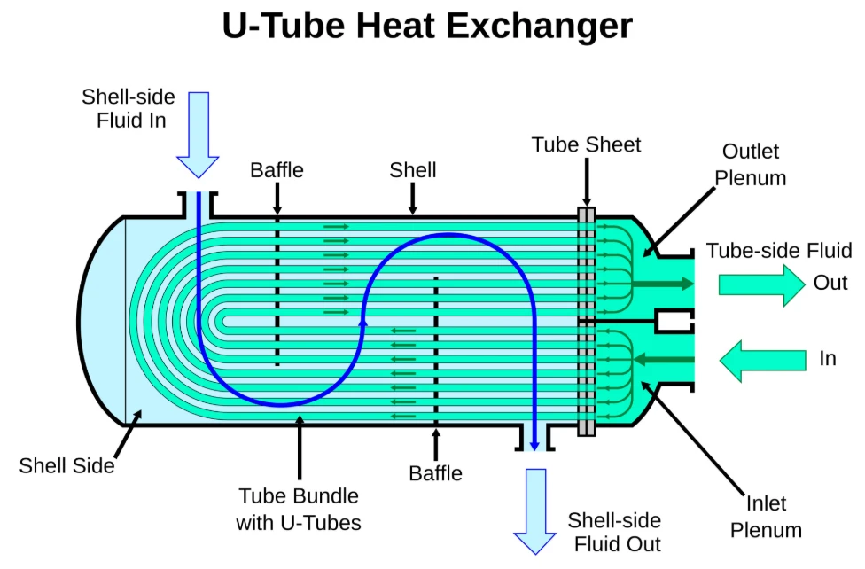
A U-tube heat exchanger uses heat transfer tubes bent into a U-shaped configuration, allowing them to accommodate relatively large temperature variations. Since the tubes can expand and contract freely, thermal stress can be effectively reduced. This design is suitable for high-temperature and high-pressure applications. However, cleaning the inside of the curved sections of the U-shaped tubes can be relatively difficult.
03
4.4 Select the Structure According to Maintenance Requirements
Different shell and tube heat exchanger designs have different requirements for disassembly, cleaning, and inspection. If the process fluid is likely to cause fouling, a design that allows convenient cleaning should be prioritized. For equipment operating continuously over long periods with limited maintenance time, available maintenance space and standby equipment should also be considered.
04
5. Select the Equipment According to Flow Rate and Pressure Drop
5.1 Determine the Flow Rates of the Hot and Cold Fluids
The flow rates of the hot and cold fluids directly affect the flow velocity and heat transfer performance inside the heat exchanger. An excessively low flow rate may reduce the heat transfer coefficient and increase the risk of sedimentation and fouling. An excessively high flow rate may increase flow resistance and the operating load on the pumps.
5.2 Select the Appropriate Number of Tube Passes
The number of tube passes determines the flow path and velocity of the fluid inside the heat transfer tubes. Increasing the number of tube passes can generally increase the tube-side flow velocity and heat transfer coefficient, but it may also increase the pressure drop. The actual design should consider fluid flow rate, tube diameter, and allowable pressure drop.
5.3 Control Shell-Side Flow Resistance
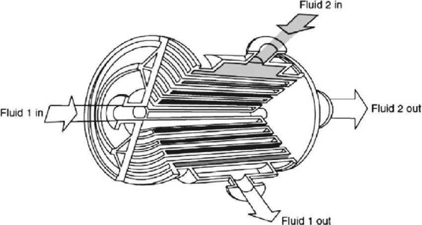
Shell-side fluid flows across the tube bundle with the help of baffles, which promote turbulence and improve heat transfer. However, improper baffle spacing or design may result in excessive pressure loss. Therefore, the baffle arrangement should be optimized to achieve a reasonable balance between heat transfer efficiency and flow resistance.
5.4 Consider the Allowable System Pressure Drop
When fluids pass through the tube side and shell side, a certain amount of pressure loss occurs. During equipment selection, the maximum allowable pressure drop of the system must be clearly defined and included in the design calculations. Excessive pressure drop may increase pump energy consumption and even affect the normal operation of the entire process system.
6. Determine the Heat Transfer Area According to Required Performance
6.1 Calculate the Required Heat Transfer Area
The heat transfer area is a key factor in determining the thermal capacity of a shell and tube heat exchanger. It is generally calculated based on the heat duty, overall heat transfer coefficient, and mean temperature difference. Proper calculation ensures that the equipment meets the required heat transfer performance.
01
6.2 Consider the Overall Heat Transfer Coefficient
The overall heat transfer coefficient is affected by fluid properties, flow velocity, tube material, tube wall thickness, and fouling resistance. Different industrial fluids and operating conditions can result in significantly different heat transfer coefficients. Therefore, the value should be determined through calculations based on actual operating conditions rather than relying on a fixed reference value.
02
6.3 Select Appropriate Heat Transfer Tube Dimensions
The outer diameter, inner diameter, length, and arrangement of the heat transfer tubes all affect the total heat transfer area and flow resistance. Longer tubes can provide more heat transfer area per tube, but they may also increase the overall equipment length and cleaning difficulty. Suitable tube dimensions should be selected according to installation space, fluid flow rates, and process requirements.
03
6.4 Allow for a Reasonable Design Margin
During actual industrial operation, fluid temperatures, flow rates, and fouling conditions may change. An appropriate design margin can be included in the heat transfer area calculation according to process conditions and expected fouling resistance. However, a larger margin is not always better, as excessive heat transfer area may increase equipment costs and reduce overall economic efficiency.
04
7. Consider Special Requirements of Industrial Processes
7.1 High-Temperature and High-Pressure Applications
In petroleum, chemical, and power generation industries, heat exchangers may need to withstand high operating temperatures and pressures. Special attention should be paid to the strength and material properties of the shell, heat transfer tubes, tubesheets, and welded joints. Equipment design, manufacturing, and inspection must comply with applicable pressure vessel regulations and relevant industry standards.
7.2 Processes Prone to Fouling and Blockage
For circulating water, industrial wastewater containing impurities, and fluids that easily form deposits, cleaning and maintenance requirements are particularly important. Tube diameter, flow velocity, and tube bundle structure should be selected according to fluid characteristics, and appropriate filtration equipment may be installed. For applications with severe fouling, regular cleaning and inspection schedules should also be established.
7.3 Corrosive Chemical Processes
Acids, alkalis, and salt solutions used in chemical production may cause different levels of corrosion to heat exchanger materials. Material selection should be based on fluid concentration, temperature, pressure, and corrosion characteristics. Where necessary, professional material assessments or corrosion tests should be conducted to confirm material suitability.
7.4 Continuous Production Processes
For production lines that require long-term continuous operation, equipment reliability and maintenance intervals are particularly important. Depending on production requirements, standby heat exchangers or parallel equipment configurations can be considered to maintain system operation during maintenance. Operating monitoring, spare parts availability, and routine maintenance convenience should also be evaluated.
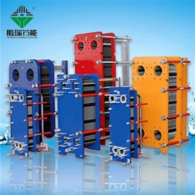
If you want to know more about heat exchanger units or are interested in purchasing, please send an email to 9988xiaoshuai@gmail.com, we will reply you in time after seeing the message!
Professional team
Our company is equipped with a high-quality after-sales service team with technical personnel as the core, and will provide timely feedback upon receiving service information notifications from users.
7x24 hours delivery
Our company provides free technical support for the products we sell and organizes technical training for relevant personnel.