


1. Determine the Required Heat Duty

1.1 Identify the Required Heat Transfer Capacity
Heat duty is the starting point for sizing a plate heat exchanger. Before selecting a model, determine the amount of heat that must be transferred to heat or cool the process fluid, usually expressed in kW or MW. If the required heat duty is underestimated, the exchanger may fail to achieve the target outlet temperature. Conversely, excessive oversizing may increase the initial investment.
1.2 Specify the Inlet and Outlet Temperatures
The inlet temperatures of both hot and cold fluids, along with their target outlet temperatures, must be clearly defined. These parameters determine the temperature driving force available for heat transfer and directly affect the required heat transfer area. Seasonal variations and fluctuations in production loads should also be considered to ensure that the equipment performs reliably under actual operating conditions.
1.3 Calculate the Heat Duty
For conventional fluids without phase changes, the heat duty can be estimated using the formula \(Q=\dot{m}c_p\Delta T\). In this equation, \(Q\) is the heat duty, \(\dot{m}\) is the mass flow rate, \(c_p\) is the specific heat capacity, and \(\Delta T\) is the temperature change of the fluid. For applications involving phase changes, such as steam condensation or liquid boiling, the calculation must also account for latent heat and other relevant heat loads.
1.4 Allow for an Appropriate Design Margin
The design should account for operating fluctuations, changes in fluid properties, and the effects of fouling over time. However, a larger design margin is not always better, as excessive oversizing may increase costs and result in unsuitable flow velocities under certain operating conditions. The appropriate margin should be determined based on process requirements, fluid cleanliness, and the supplier's thermal calculations.
2. Determine the Flow Rates of Both Fluids
2.1 Provide Accurate Design Flow Rates
The flow rates of the hot and cold fluids are essential parameters in plate heat exchanger selection. They are commonly expressed in kg/h, t/h, or m³/h. Flow rates affect the fluid velocity within the plate channels, the heat transfer coefficient, and the pressure drop. Normal, maximum, and minimum operating flow rates should be provided so that the exchanger can accommodate different operating conditions.
2.2 Understand the Relationship Between Flow Rate and Heat Transfer Efficiency
Increasing fluid velocity appropriately can enhance turbulence and improve the convective heat transfer coefficient. However, it can also increase pressure drop and pumping energy consumption. If the velocity is too low, deposits and fouling may accumulate more easily, reducing long-term heat transfer performance. The final velocity should be determined by considering fluid properties, plate channel geometry, and the allowable pressure drop.
2.3 Match the Flow Rates on Both Sides
The flow rates of the hot and cold fluids do not necessarily need to be equal. They should be determined according to the heat duty, specific heat capacities, and required inlet and outlet temperatures of both fluids. Even when the flow rates are identical, differences in fluid properties may result in different temperature changes. The supplier should perform thermal calculations to determine the appropriate number of plates, channel arrangement, and pass configuration.
2.4 Consider Flow Rate Variations
For production systems with fluctuating loads, the expected range of flow rate variations should be clearly specified. The heat exchanger should maintain appropriate heat transfer performance and pressure drop under common operating conditions while avoiding problems such as uneven flow distribution at low loads. If the operating range is wide, the suitability of control valves, variable-frequency pumps, or bypass lines should also be evaluated.
3. Calculate the Required Heat Transfer Area

3.1 Understand the Role of Heat Transfer Area
Heat transfer area is one of the key factors determining the overall size of a plate heat exchanger. Under otherwise identical conditions, a higher heat duty or a smaller effective temperature difference generally requires a larger heat transfer area. In plate heat exchangers, the required area is typically achieved by adjusting the number of plates or selecting an appropriate plate design.
3.2 Calculate the Required Heat Transfer Area
For preliminary sizing, the required heat transfer area can be estimated using the formula \(Q=UA\Delta T_{\mathrm{lm}}\). In this equation, \(Q\) is the heat duty, \(U\) is the overall heat transfer coefficient, \(A\) is the effective heat transfer area, and \(\Delta T_{\mathrm{lm}}\) is the logarithmic mean temperature difference (LMTD). The actual calculation must also account for the flow arrangement, temperature correction factors, fouling resistance, and fluid properties. The final model should not be selected based on this formula alone.
3.3 Evaluate the Effect of Temperature Difference
When the effective temperature difference between the hot and cold fluids is relatively large, a smaller heat transfer area may be sufficient for the same heat duty. Conversely, applications requiring close outlet temperatures or a small terminal temperature difference generally need a larger heat transfer area. During selection, the feasibility of the target outlet temperatures should be verified to ensure that the requirements are thermodynamically achievable.
3.4 Determine the Number of Plates Through Thermal Calculations
The number of plates should be determined according to the required heat transfer area, the effective area of each plate, and the plate geometry. Adding plates generally increases the total heat transfer area, but it also changes the number of flow channels, fluid velocity, and pressure drop. The final plate count should be determined through professional thermal calculations rather than estimated solely from the equipment's appearance or general experience.
4. Evaluate Fluid Properties and Plate Materials
4.1 Identify the Basic Fluid Properties
Before selecting a plate heat exchanger, provide the fluid name, concentration, density, viscosity, specific heat capacity, and thermal conductivity. These properties affect fluid flow, the heat transfer coefficient, and pressure drop inside the exchanger. For fluids whose properties vary significantly with temperature, the relevant operating temperature range should also be provided to improve calculation accuracy.
01
4.2 Select Plate Materials Based on Corrosion Resistance
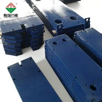
Plate materials should be selected according to the chemical composition, concentration, temperature, and corrosiveness of the fluids. Stainless steel grades 304 and 316 are suitable for many common applications, but they are not appropriate for every corrosive environment. Titanium or other materials may need to be considered for seawater or chloride-containing applications. For highly corrosive fluids, material compatibility should be verified by qualified professionals under the specific operating conditions.
02
4.3 Select Plate Geometry Based on Fluid Viscosity
High-viscosity fluids generally produce greater flow resistance, so special attention should be paid to plate corrugation patterns, channel design, and allowable pressure drop. For fluids containing particles or fibers, or those prone to fouling, channel width, blockage risks, and cleaning methods should also be evaluated. Simply increasing the number of plates cannot solve every problem, as an unsuitable channel design may still compromise operating performance.
03
4.4 Confirm Gasket Compatibility
For gasketed plate heat exchangers, gasket material affects temperature resistance, chemical compatibility, and service life. Common gasket materials include EPDM, NBR, and FKM, but their suitability depends on fluid composition, operating temperature, and the manufacturer's specifications. Incompatible gaskets may deteriorate, leak, or require frequent replacement. Therefore, gasket selection should be considered together with plate material selection.
04
5. Control Operating Pressure and Allowable Pressure Drop

5.1 Specify the Operating and Design Pressures
Operating pressure refers to the actual pressure during normal operation, while design pressure is the pressure used as the basis for equipment design. Both sides of the exchanger should have clearly specified operating pressures, design pressures, and possible pressure fluctuations. The rated pressure capacity must meet the design requirements and remain compatible with the allowable limits of the plates, frame, gaskets, and connections.
5.2 Define the Allowable Pressure Drop
Fluid flowing through a plate heat exchanger experiences a pressure loss, which should be calculated separately for the hot and cold sides. The allowable pressure drop depends on the system piping resistance, pump head, and process requirements rather than a universal fixed value. Excessive pressure drop can increase pumping energy consumption and may prevent the system from achieving the required flow rate.
5.3 Balance Heat Transfer Performance and Pressure Drop
Increasing fluid velocity generally improves heat transfer but may also significantly increase pressure drop. Therefore, the selection process must balance heat transfer area, fluid velocity, channel configuration, and pumping energy consumption. If the system is particularly sensitive to pressure loss, the supplier can evaluate alternative plate designs, channel arrangements, or pass configurations.
5.4 Check Abnormal Operating Conditions
In addition to normal operating conditions, startup, shutdown, rapid valve operation, and pressure fluctuations should be considered. Systems that may experience water hammer, thermal shock, or frequent cycling require an assessment of the exchanger and associated piping under these conditions. Appropriate control and protection measures should be implemented when necessary to reduce the risk of damage to the plates and sealing components.

6. Determine the Equipment Dimensions Based on Installation Space
6.1 Measure the Available Installation Space
The external dimensions of the plate heat exchanger must be compatible with the available installation area. Before selection, confirm the equipment's length, width, height, foundation dimensions, and inlet and outlet piping arrangements. In addition to the space required for installation, sufficient room should be provided for transportation, lifting, and maintenance.
6.2 Allow Sufficient Space for Plate Removal
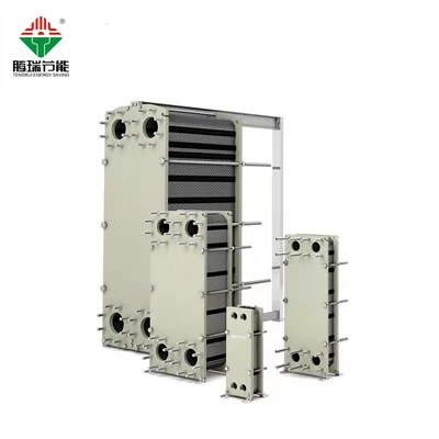
For a gasketed, demountable plate heat exchanger, maintenance generally requires loosening the tightening bolts and moving the movable pressure plate and plate pack along the carrying bar. Therefore, sufficient clearance must be provided in the direction required for opening the unit. Even if the exchanger fits into the available space, inadequate clearance may make cleaning, inspection, and plate replacement difficult.
6.3 Confirm Connection Sizes and Piping Orientation
The inlet and outlet locations, connection sizes, and connection types should match the site piping design. During selection, verify the flow directions of both fluids, the available piping space, and the equipment's installation orientation. Poorly planned connections may increase piping modification costs and complicate installation and maintenance.
6.4 Consider Future Expansion Requirements
If production capacity is expected to increase, inform the supplier of the anticipated future flow rates and heat duty. Some gasketed plate heat exchangers can accommodate additional plates to increase heat transfer area, but expansion is limited by frame length, clamping dimensions, design pressure, and flow configuration. Not every model can be expanded indefinitely, so the available expansion capacity should be confirmed before purchase.
7. Consider Operating Conditions and Maintenance Requirements
7.1 Evaluate Continuous Operating Conditions
For production systems that require continuous operation, selection should focus on reliability, cleaning intervals, and ease of maintenance. Over time, fouling, sediment buildup, and gasket aging may reduce heat transfer performance. Selecting appropriate plate geometry and materials according to the process conditions can help reduce maintenance risks and unplanned downtime.
7.2 Assess Fouling and Blockage Risks
If the fluid contains suspended solids, minerals, or substances that tend to accumulate, the risks of fouling and blockage should be evaluated in advance. These applications require particular attention to channel dimensions, fluid velocity, filtration measures, and cleaning conditions. A suitable filter may be installed upstream when necessary, but its filtration rating and maintenance requirements should be determined according to the fluid characteristics.
7.3 Determine Cleaning and Maintenance Methods
During selection, determine whether a demountable design or another type of construction is appropriate for the application and site conditions. Gasketed, demountable plate heat exchangers generally allow the plate pack to be opened for mechanical cleaning and inspection. Chemical cleaning may also be suitable for certain applications. Any cleaning agent used must be compatible with the plate and gasket materials.
7.4 Evaluate Lifecycle Costs
Purchase price is not the only factor in determining the economic value of a heat exchanger. Operating energy consumption, cleaning expenses, spare parts, and downtime losses should also be considered. An undersized unit may fail to meet the required heat duty, while an oversized unit may increase the initial investment and space requirements. Comparing equipment costs with long-term operating expenses helps identify the most economical option.
8. Confirm the Final Model Through Professional Calculations
8.1 Prepare Complete Process Data
Before requesting a quotation, prepare the fluid names, flow rates, inlet temperatures, target outlet temperatures, operating pressures, and allowable pressure drops for both sides. Additional information should include fluid properties, corrosiveness, fouling tendencies, and operating schedules. The more complete the data, the more accurately the supplier can calculate the required heat transfer area and equipment dimensions.
8.2 Request Detailed Selection Calculations from the Supplier
The supplier should perform thermal calculations based on the actual operating conditions and provide key data, including heat duty, effective heat transfer area, number of plates, pass configuration, and pressure drop on both sides. For critical or complex applications, the fluid property data, fouling resistance, and design assumptions used in the calculations should also be reviewed. The suitability of the equipment should not be judged solely by its model number or external dimensions.
8.3 Verify Design and Manufacturing Requirements
Before confirming the final model, check the design pressure, design temperature, plate material, gasket material, connection specifications, and applicable standards. For corrosive, flammable, or otherwise hazardous process fluids, confirm that the equipment meets the relevant safety and compliance requirements. All critical parameters should be clearly documented in the technical agreement or purchase specifications.
8.4 Confirm Suitability Under Actual Operating Conditions
Equipment selection should account not only for rated conditions but also for typical operating scenarios, including minimum load, maximum load, and seasonal variations. For processes with strict outlet temperature requirements, verify the heat transfer capacity and control strategy under different operating conditions. The final model and dimensions should be confirmed only after completing the necessary calculations and verifying the site installation requirements.
If you want to know more about heat exchanger units or are interested in purchasing, please send an email to 9988xiaoshuai@gmail.com, we will reply you in time after seeing the message!
Professional team
Our company is equipped with a high-quality after-sales service team with technical personnel as the core, and will provide timely feedback upon receiving service information notifications from users.
7x24 hours delivery
Our company provides free technical support for the products we sell and organizes technical training for relevant personnel.
